Location: Moranbah, QLD
Client: Redpath/Anglo America
Status: Drifts were fully completed in September 2015, first long wall coal expected mid 2016
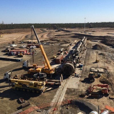
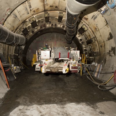
The Grosvenor mine development is a $2 billion greenfield project that will result in a state of the art long wall mining facility. A key component of the development was the construction of two 1km segment lined tunnels to provide coal seam access. The geological conditions in this area were known to be very challenging and drift stability for the life of mine was a serious concern during pre-development planning. With this in mind Anglo America proceeded with a revolutionary step in the Coal Industry and Grosvenor became the first coal mine to ever use a TBM for the drift construction. Redpath Mining was awarded the drift construction contract and an 8m diameter EPB Robbins TBM was selected for the excavation.
Key Benefits of TBM Use
• Significantly reduced excavation time compared to standard road header construction
• Increased profile strength by using segment lining to mitigate the weak geological conditions
• The use of EPB (Earth Pressure Balance) provided a safe method to traverse through methane rich coal seams and removed construction worker exposure to ground subsidence
Challenges
The use of a TBM in the Australian Mining Industry was an innovative option. However it was also the first time this technology had been applied in a mining environment. To modify the TBM so it could work safely and legally in the QLD Coal Mining Industry was a significant challenge. There was a lot of special regulations and restrictions that were not typical of a standard tunnel project.
Use of the same TBM was required to cut two individual drifts that were located 2km apart on the surface. This added several additional phases to the project which consisted of extraction, transport and rebuild. The drifts were 1:6 and 1:8 respectively so both the excavation and extraction phases were performed on a steep gradient. This presented a challenge in the field and for office calculations.
Construction
The construction program for the two tunnels was broken down into several distinct stages. As the Project Surveyors, we had different primary roles for each phase of the project. The Survey team consisted of four Surveyors on a 24/7 FIFO roster. This meant that there was always a dedicated Surveyor onsite.
Initial TBM Build and Launch
• Assist with the setout and construction of all site compound and TBM surface infrastructure
• Check the launch ramp to ensure all tolerances were met
• Setout and check the steel set thrust beam and shotcrete for the first push
• Installation and coordination of the survey network control using a Leica TS15i 1“. Computations were done via COMPNET Least Squares adjustment
• Assist with the PPS guidance installation and shield calibration survey to determine the guidance system parameters
• Installation of thrust brackets once the TBM was at the face. This involved setting 12 thrust brackets at equal chainages and perfectly square to the thrust rams on a 1:6 gradient. This was a critical part of the launch as any weakness or misalignment would put excessive stress on a single bracket and shear the weld. Logistically this was difficult as the brackets could only be installed once the TBM shield had advanced past the thrust beam.
Excavation
• Provide PPS guidance support to the operators and ensure the system was reporting accurately. A check and record system was developed to ensure independent measurements and observations were taken frequently to check the integrity of the guidance system.
• Outbye primary tunnel control was rigorously checked and coordinated on a weekly basis.
• Every second guidance roof station was checked via an independent traverse from the primary tunnel control. The maximum adjustment made was 10mm.
• Every ring in the tunnel was surveyed and the tolerance checked using Lynton Surveys tunnel conform software. This provides an easy to read graphic that shows the as constructed position vs the design location.
• In addition to absolute position of the ring, the elongation was also checked. A custom written excel sheet was used to determine the as constructed ring centre and then compare the radial distances to a design length.
Extraction, Transport and Rebuild
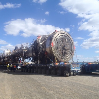
The extraction phase was in many ways the most challenging of the entire project. Removal of an entire TBM on such a steep gradient was another first for the industry. At the conclusion of the initial excavation a series of lifts and jacks were installed to remove the TBM backwards out of the tunnel. The cutter head and other various components were recovered once the TBM was back on the surface. To assist with this phase survey support was provided for the following:
• Topographic survey and route design for the TBM surface transport. This including space checking for vertical obstacles and checking the radial restrictions for a 60m long mass transport unit.
• Precise mechanical surveys to check the final TBM core location and setout to align the lifting jacks.
• Setout for the life of mine conveyor structure during the TBM extraction. A virtual profile was created to account for any tunnel misalignment and the dynamic chain angle of the conveyor. This method ensured that once installed the belt centreline would run true.
• Elongation checks of the TBM shield during rebuild. Multiple surveys were taken during the welding phase to monitor any elongation of the shield, appropriate bracing was applied to mitigate this variable.
Second Excavation Phase
Having the chance to repeat a matching sequence is unusual in the construction industry. However on Grosvenor this opportunity was presented. An enormous amount of learning was taken away from the first excavation and multiple changes were made to improve efficiency for the second excavation. Some of the key advances for Survey operations were:
• Installation of a custom made cable reel and tray to remove the guidance wiring from the wall and reduce the chance of it being damaged
• The creation of a laser guided system combined with a pre-fabricated template to allow accurate setout of the tunnel conveyor belt. Significant downtime was removed by having a very well aligned conveyor.
• A laser guided system for service pipe construction was developed so that personnel could visibly align the pipe bracket.
• Custom made shields were installed to protect the PPS motor prisms from dirt and waste.
The second excavation was regarded as a huge success. A successful breakthrough was made on the 15th of February 2015, with a total time for this phase of 16 weeks from launch. This was a significant improvement on the first tunnel which took 24 weeks and was 200m shorter!
Project Statistics
• TBM – ‘Lucia’ a Robbins 8m diameter Earth Pressure Balance, 1500 tonnes, 125m long
• CV Drift - length 903m, 1:6 gradient. Driveage time 24 weeks
• MM Drift - length 1124m 1:8 gradient. Driveage time 16 weeks
• Final Profile – 7m internal diameter, segment lined tunnel with precast floor unit
• Combined Excavation Volume – 90,000m3 (excluding launch ramp and armco section)


