Location: Gerringong NSW
Client: Fulton Hogan
Status: Bridge Completed December 2014. Project Completed August 2015
The Gerringong Upgrade Project consists of a 7.5 km, 4 lane divided carriageway and provides grade separated interchanges at each of the existing entry points to Gerringong off the Princes Highway, located south of Kiama on ‘the bends’ to Toolijooa Rd at Foxground. The design intent of the Highway upgrade was to ease the congestion during holiday periods and other high traffic times.
Challenges
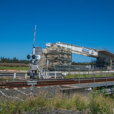
The South Coast rail network for both passengers and heavy freight ran on a single line through Gerringong. Any traffic exiting the highway into the township of Gerringong was subjected to barrier rail crossings. The requirement was to construct a bridge to cross the Railway, at a high angle of skew (approximately 60 degrees), with the existing Fern Street traffic to be maintained throughout the construction. The initial concept design proposed was a Super T Superstructure supported by hammer head piers and a portal pier that spanned the railway corridor. The Super T proposal was quickly ruled out, as Fern Street would have to be closed for one year. A concrete box girder option (constructed by incremental launching) was considered a major improvement by Fulton Hogan, and was put forward to RMS. This was accepted as the final design.
Construction
The bridge layout
• 350m long concrete box girder that consisted of 16 incrementally launched segments.
• 6 permanent piers
• 1 temporary pier
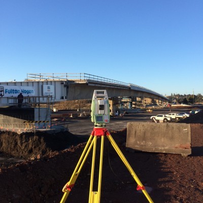
Our surveyors and Fulton Hogan had the task of creating a 3d model of the bridge and implementing a technique to set out the girder components in the casting yard. Each segment was built in sequence such that it would reside in the design location once the superstructure was launched.
A tight control network was needed and a traverse technique was implemented, by undertaking a minimum 12 sets of observations, with the final result calculated using least squares and projected to plane scale factor.
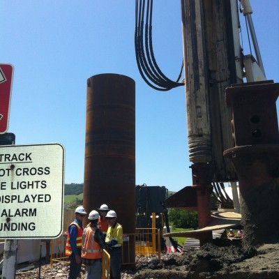
Before the construction of the bridge could start, a temporary road was built to detour the existing Fern Street traffic around the construction site. The first stage of the bridge construction consisted of raising the existing, rock surface ground level, as it was subject to frequent flooding. Pile depths of 26m and diameter sizes of up to 1.8m, were needed for the abutment and pile foundation, due to the soft ground layers that were up to 8m deep. Construction of the southern abutment piles and casting bay commenced first, as it would allow for the Superstructure to be cast and launched while the northern piers and abutment were still in the process of construction.
The casting bay layout was a row of unreinforced concrete piles, founded on stiff gravel underneath outer strip footings. These supported the formwork for the wings 28 x 600 diameter piles underneath 2 spine beams drilled to bedrock and formwork mould, consisting of approximately 200T of temporary steelwork fabricated at UCCA in China. The casting bay was a mould where the 16 segments were formed in mostly 22m in length before being launched. The spline beam levels had to be setout to 0.2mm and conformed to 0.5mm.
The superstructure was made up of 16 segments with 2 abutment diaphragm segments and 6 pier diaphragm segments. The concrete was done in 2 stages; the first pour was the bottom and web concrete, the second stage was the top flange. The bearings top attachment plates were calculated and setout in the bottom of the girder, so they would line up exactly with the pot bearings on the abutments and piers. This attachment plate calculation consisted of measuring the arc distance from the front of the first segment, the total concrete shrinkage to date, estimated future shrinkage and the bearing rotation as each of the pot bearings were orientated to pier threes fixed bearing, which was placed in the centre of the bridge.
The superstructure was pushed out of the casting bay along the spline beams by 2 launching jacks, that had 2 banks of 3 horizontal pushing rams with a combined capacity of approximately 1000T and twin vertical rams, with a combined lifting capacity of 2200T. On the front of the first segment there was a launch nose that succesfully provided guidence for the superstructure over the piers and abutment to its final location. While the bridge launching was in operation the pier deflection and girder movement had to be monitored. The pier deflection was monitored from a nearby location using mini prisms that were attached to the top of the piers and abutments. The girder was monitored and guided by mini prisims that were bolted to the edge of the deck.
The program achieved a minimum 8 day cycle, made up of a 52 hour working week. In total the bridge construction took 60,000 man hours worked over a 22 month period, 4 MTIs and no LTIs achieving a MTI frequency rate of 0.0067%. Each girder segment had 6000 individual reinforcement bars, 32 tonnes of steel reinforcement, 8 kilometres of strand and 200 m3 of concrete.


